Overview
The location indicator control displays a configurable axis in the main
3D display and (optionally) a bearing point. The user interface is
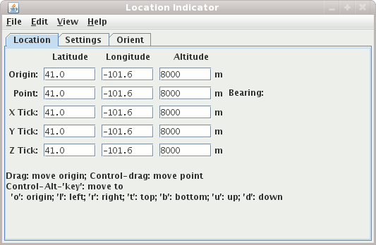
composed of three tabs. The first displays the position of the origin and
the bearing point.

Image 1: Location Indicator Location Tab

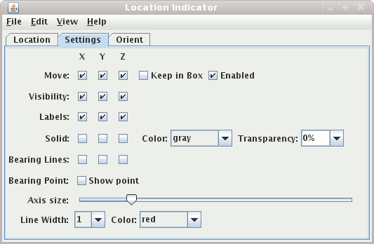
Image 2: Location Indicator Display Tab

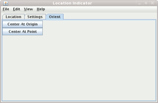
Image 3: Location Indicator Orient Tab
To change the origin click and drag in the main display. To show and/or change the bearing point do a control-drag in the main display. The x/y/z locations of the bearing point are shown on the origin axis as tick marks and, optionally, as longitude/latitude/altitude readouts.
Properties
- Location Tab
The Location tab shows the location of the origin point, the bearing point and the 3 tick axis points. You can set the value of the origin or bearing point directly by entering the value in the appropriate text field and pressing return.
- Display Tab
The display tab allows you to configure the display. You can:
- Constrain along which axis points are moved with the
Movecheckboxes. - Constrain the movement to be within the main 3D bounding box.
- Disable the dragging of points with the
Enabledcheckbox. - Turn on/off the visibility of labels.
- Turn on the display of a solid plane along any of the axis with the
Solidcheckboxes. You can also change the color and the transparency of the plane. - Show or hide the bearing lines. These are dashed lines from the respective axis to the bearing point.
- Turn on/off the display of the bearing point with the
Show pointcheckbox. - Expand/contract the length of the origin axis.
- Set the line width, color, etc.
- Constrain along which axis points are moved with the
- Orient Tab
You can center the display at the origin or at the point of the location indicator. More to come.


