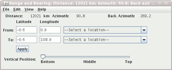
When the range and bearing control is first created a range and bearing line, shown in red in the above figure, is added to the main view window. The distance and azimuth values are shown on the Legend in the main view window, and at the top of the range and bearing control window. The latitude-longitude position values of the end points are also shown. Computations are based on the WGS-84 reference ellipsoid, using computation code from the U.S. National Geodetic Survey.
Note The line shown on the display is not the great circle path connecting the end points. The values are computed for a great circle path on the ellipsoidal earth, using the numerical latitude and longitude values, not the line on the display. The line shown in the display is a straight line on whatever map projection you happen to have; usually it will not coincide with the great circle line.
Note If you change the map projection, an existing range and bearing map line will stay at the same location in the display, hence the end points on the map are in new locations. The distance, azimuth, etc. values in the control window reflect the latitude-longitude positions in the control window and hence do not match the display picture until an end point is moved by hand.
- Positioning the line
You can re-position the end points of the line in the display by dragging the end points with the left mouse button, or by selecting positions from the pull-down menus. You can change what pre-defined positions are used with the
Edit->Set Locationsmenu.You can move the entire set of selector line and both end points at once by dragging mouse pointer on the the square at the center of the line. The orientation across the display is maintained while the line moves.
- End points
You can enter the latitude and longitude values of either end point of a line. Click in the text window whose value you want to save. Use the backspace key to remove unwanted numbers, and enter the new values. Then pressing the Enter key will move the end point of the line to the new position, and show the new distance and azimuth values.
- Vertical Position
This slider allows you to set the vertical position of the range and bearing line.


