


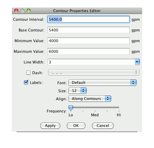
Contour Interval determines the spacing (difference in value) between contours. Set it to a single value to specify a regular interval between contours. You can specify irregular contour intervals with a semi-colon separated list of the values. For example:
5400;5460;5800
would only show the 5400, 5460 and 5800 contour lines.
You can also specify different contour intervals for different ranges with the following syntax:
cint1/min1/max1;cint2/min1/max2;....;cintn/minn/maxn
For example, for geopotential heights:
30/0/4200;60/4200/8600;120/8600/24000
would draw contours at 30 gpm between 0 and 4200, 60 gpm between
4200 and 8600 and 120 gpm between 8600 and 24000.
To show a single contour line, specify the contour interval, min and max as the same value. For example:
5400/5400/5400
would only show the 5400 line.
Base contour is the value on which all contours are based. All contours will be integer multiples of the contour interval from the base value. For example, with a base value of 0 and a contour interval of 3 contours would be created at ..-6, -3, 0, 3, 6... A base of 1 with that interval would create contours at ..-5, -2, 1, 4, 7... The base value need not be the lowest contour level on a plot, or inside the range of values plotted; it is only a computational reference point. The base contour value is also used for controlling which lines are dashed.
Minimum value is a limit below which no contour lines are shown. The minimum may be larger than the base value, so that the base value may never appear on a plot.
Maximum value is an upper limit above which no contour lines are shown. The minimum and maximum values need not match contour line values; they are only limits.
Line width sets the line width (in pixels) of the contour lines and labels.
If Dash is checked, values less than the base value are dashed. If base is set higher than maximum value, then all lines are dashed. You can set the dash line style using the selection widget.
You can toggle the labels by clicking the Labels check box. You can set the font, font size, label alignment and label frequency using the widgets. The default values for these can be set in the User Preferences under the View tab.
Click on OK to set the values you want and close this window. Click Apply to set the values but leave this window open.