

| 2.3.0 | Connecting to a Data Source on a Remote Server |
| 2.3.1 | Selecting the display to be made |
| 2.3.2 | To make a plot of 3D data |
| 2.3.3 | Subsetting Times |
| 2.3.4 | Spatial Subsetting |

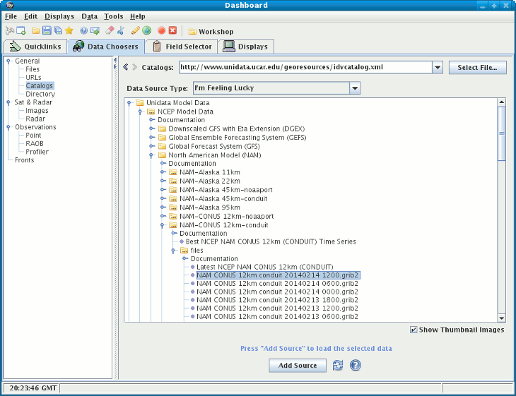
A tree view of the catalog will be displayed. Open one, such
as the "NCEP NAM 80km CONUS model data (real and near time)",
by clicking on one of the tab icons
( ).
).
The list of this model's run times appears. Click on one time to select it, and then click on the Add Source button. You have selected this model run's output to be accessible by the IDV.
 )
to expand that category list. A list of all 2D grid
parameters in the data source appears.
When one of the fields is selected the list of applicable displays will be
shown. For a complete list of example displays, see
Example Displays.
Try creating a Contour Plan View by selecting that display
in the list and clicking on the Create Display button.
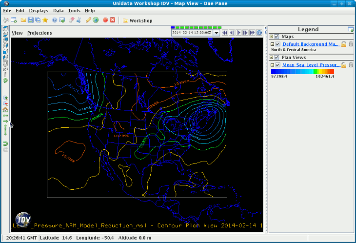
The display will be created and shown in the main window. The
display's legend should also be shown. You can bring up the control window by right
clicking on the name in the legend and selecting
Control Window from the popup menu.

Display types suitable for this parameter are listed in then
Displays panel.
Select Contour Plan View and click on the
Create Display button.
The initial plot is at the lowest level in the data grid, such as 1000 millibar in this example. To shift the level to other levels:
Control Window
to bring up this display's Control window
To zoom, rotate or pan this 3D display, see Zoom, Rotate, and Pan. Rotate the display by dragging with the right mouse button. (you see that the 500 millibar contours are above the surface). The key combination Ctrl-R will restore the display to the original overhead view.
To toggle on the time animation loop, use the Run/Stop icon in the animation control. Read more about Time Animation Widget.
To remove an existing
display, use the File->Remove Display menu of the
display's control window or the popup menu.
To make time selections that apply to all data in one data
source, double click on the data source name in the left panel
of the Field Selector window to bring up the
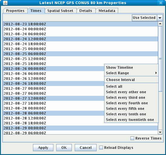
Data Source Properties editor. Click on the Times tab to subset the times.

To make time selections for one field, use the Times selector in the lower right panel of the Field Selector, under the Displays panel, after you select the field, and before you create the display. This will override the default times for the data source.
Spatial Subset tab of the Data Source Properties or
the Field Selector. This works similar to the times subsetting where
you can set the property for all fields in the Data Source or
override the default for a particular field.
For more information on time and spatial subsetting, see the Data Source Properties page of this User's Guide.